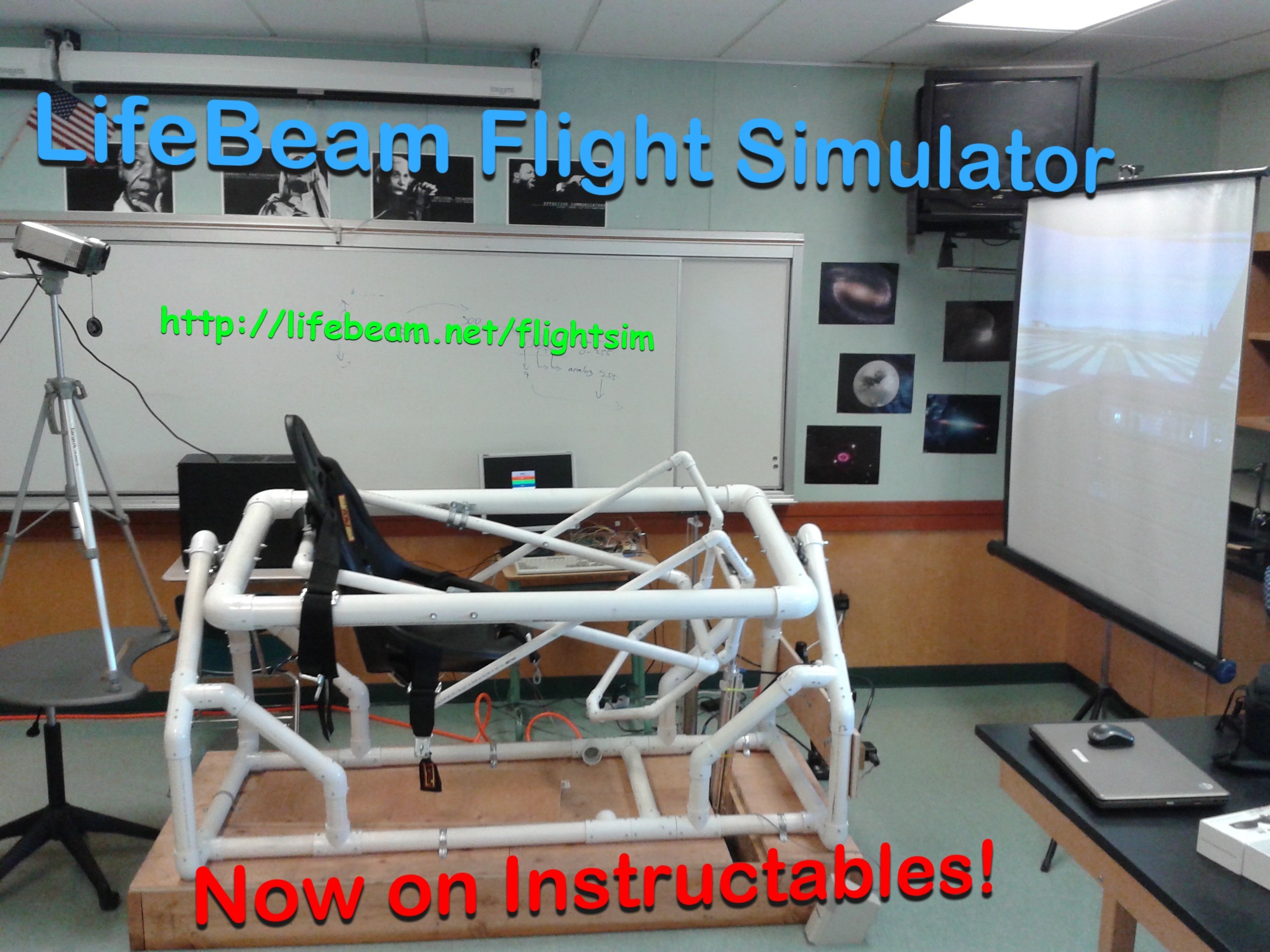
The LifeBeam Flight Simulator is a full setup of equipment that runs simultaneously and collaboratively. The data is first sent from the graphics computer through a custom software program that acquires game data. The game data is scaled and converted into specific coordinates for the pitch and roll axis. The program sends out the final signal which is received by an Arduino (microcontroller). The Arduino has a complex program that combines the serial commands and parses certain values to calculate a voltage which is then converted into PWM. The PWM is sent to a low-pass filter circuit which smooths the PWM into analog voltage. The voltage is sent to a Pneumatic Valve Amplifier which controls the pneumatic cylinders to make the simulator platform move accordingly with the user's control. A linear potentiometer measures and regulates the movement of each pneumatic cylinder.
Below, we give you a visual tour of all the parts that are described in the concept mentioned above.
Control Components
The Arduino is an essential part of this project because it is the microcontroller that generates the signal to the Flight Simulator.
The Arduino is programmed to recieve serial commands from a computer at 57600 times per second. These commands tell the Arduino to give out a specific voltage in PWM (Pulse Width Modulation) to the Servo Amplifiers in the control box.

Our Flight Simulator's main structure is the physical foundation of the project. It consists of a racing seat mounted on a series of schedule 40 PVC pipes. We have layered certain parts of the PVC tubing. All pipers are secured with screws. The PVC structure rests on a large wooden base, which is where the pneumatic cyliners are mounted.

We have a dedicated high-end gaming computer built specifically for the FlightSim. This computer features an AMD TriCore 3.4 GHz Processor with 8GB RAM. This computer runs the gaming software that provides the visualizations for the pilot, and simulteously run the Custom FlightSim software which controls the pneumatics on the motion simulator.

Motion Components
The pneumatic cylinders are the long metal rods with small tubes connected to them. When pressurized, these steel cyliners move up and down to move the flight simulator. These are bolted to the PVC structure.
The pneumatic cylinders are connected to servo valves, which are components that can dynamically change the amount of pressure in the cylinders using electricity.

This box contains the Power supply, Arduino, PWM regulator, and Servo Amplifiers. The power supply provides electricity to all circuit boards. The Arduino is mentioned above. The PWM regulator is a custom-made circuit that smoothens the Arduino's 5v PWM to ±10 volts. The Servo Amplifiers are PID circuits that take a control signal and feedback signal, and uses it to control the pneumatic cylinders.

This is the main component of the pneumatic setup. This electric compressor stores up to 8 gallons of air @ 130 psi. This is the unit that pressurizes the pneumatic cylinders for usage. The air compressor maintains the air pressure by itself. When pressure is decreasing, the compressor automatically becomes activated to refill the tank.

Display Components
For the display, we used the latest 3D technology: a 120hz 3D DLP projector. Using wireless active shutter glasses, the passenger is able to sense visual depth. Scenery also looks better in 3D. The graphics are exceptionally crisp since we used an HIS 6770 video-card for the gaming computer.

High quality BOSE speakers are implemented for realistic sound effects. Speakers are mounted on the wooden base of the structure.

The tactile trasducer is a high-power vibrating subwoofer which is mounted directly under the racing seat. With this setup, the passenger can literally feel the engine rumble. Research shows that vibrations can simulate certain G-forces. This implementation is added to enhance flight experience.
